
Wednesday, October 28, 2009
And the walls come up...
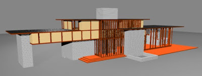
I explained earlier that I HAD to do all of the framing. With the cement (cemesto) board in place, you can see where the framing becomes part of the esthetic. It is internal as well as external. In most (maybe all) of Wright's homes, plaster was dyed, not painted. Some unions didn't like this. Amusing to say the least.
Tuesday, October 27, 2009
A peek into the future...
It's been amazingly productive these past few days.
Stairs: These are the hardest things ever! Thank goodness I was able to use the software's 'array' feature.
TV Nook & closet: I had to reconstruct these to match the current house, not as specified in the plans.
Fireplace: Now this actually looks like it's been used.

Stairs: These are the hardest things ever! Thank goodness I was able to use the software's 'array' feature.
TV Nook & closet: I had to reconstruct these to match the current house, not as specified in the plans.
Fireplace: Now this actually looks like it's been used.
Ultimately the completed house model will have this level of detail, inside & out:

Monday, October 26, 2009
Geek info...
Hardware:
Model Name: MacBook Pro 17"Processor Name: Intel Core 2 Duo
Processor Speed: 2.6 GHz
Number Of Processors: 1
Total Number Of Cores: 2
L2 Cache: 6 MB
Memory: 4 GB
Bus Speed: 800 MHz
Drive Capacity: 297.77 GB
Mac OS X: Version 10.5.8
Software:
Windows OS: Parallels running Windows XP Professional3D Software: 3DS Max 6 w/Open GL
Renderer: Mental Ray
Yup! I'm doing this project on a MAC.
Today is 'fix it' day...
In this model, I build each component (slab, block, etc.) in individual files. When the components are completed, I import them into what I call the 'test' file. It's in this file that I can determine if the components fit correctly with the already existing ones.
Today, I am correcting the TV nook and livingroom closet. The plans I have call for a width of 3'6-1/2" for the TV nook. In reality, I have figured out it is only 1'6" wide. Quite a difference. So, I have to correct that, and then move the closet (which is next to it) accordingly. If I hadn't been familiar with the house, I would have missed that.

Today, I am correcting the TV nook and livingroom closet. The plans I have call for a width of 3'6-1/2" for the TV nook. In reality, I have figured out it is only 1'6" wide. Quite a difference. So, I have to correct that, and then move the closet (which is next to it) accordingly. If I hadn't been familiar with the house, I would have missed that.

Adding glass...
As one might expect from a Wright home, there is alot of glass. The Penfield house is no exception. The following illustrates that:

Here, the windows are in place with the framing:


Here, the windows are in place with the framing:

Thursday, October 22, 2009
Thanks to the Penfields...
Sheet #6 that I got today is exactly what I needed. Thanks so much. Now I can proceed with the steps (gulp). The copy of the rendering that Lou did is particularly interesting. I like the house the way it is now. Lou dared to ask Mr. Wright to make a design change? Yikes! And he survived?
From the ground up...
Concrete Work
It made sense to start with the slab and then start laying block. There's quite a bit on the lower level; very little on the upper.

Framing
Framing was a chore. Since it isn't hidden behind wallboard on walls or ceilings, I HAD to do it. Luckily it's all 4"x4"s.


That's alot of timber!
After the 'grid'...
Once I got the grid situation under control with my calculation cheat-sheet, I had another immediate problem: what scale do I work at? It seemed ridiculous to work from scaled drawings only to have to re-scale them for the computer. In the interest of time, efficiency and accuracy, there was only one way to go... FULL scale.


Wednesday, October 21, 2009
The drawings...
When I got the drawing copies from CMU, they were legible. Some of them, barely. The majority of the drawings are 'scaled': 1/4" = 1'; 3/4" = 1'. I borrowed an architect's scale from a friend and proceeded with the project. Do the slab 1st since that was what the house rests on. OK. Measure. Measure. Measure. Done. Let's lay the block. Measure. Measure. Measure. Block is done. Let's marry the block to the slab. Oops. They don't match. Go back and re-measure. Dimensions are OK. Why don't they meet? It finally dawns on me... there's 'creep' in the copies horizontally because these drawings are copies of copies of copies. At least 3rd generation. Crap!
Upon further inspection of the drawings, Mr. Wright states that the house is to be laid out on a grid of 4'4". In addition, he's kind enough to supply the grid... A-Z on the horizontal; 1-10 on the vertical. Yikes! I'm reduced to having to work from a grid in addition to the fact that everything is 'scaled' not dimensioned. Right now I'm imagining what the builders went through building this place. So, I make myself a chart: 'A' on the grid is 0'0"; B is 4'4"; C is 8'8"... and so on. I got an architect's feet/inches app for my iPhone so I could do the conversions. So if I had a dimension of grid 'G' plus 4", I had to calculate that 'G' was 26'0" and add 4" to get 26'4". It worked.
So that is how I've tackled that problem. Time to move forward.
Why the Penfield House?
In the early 1970’s, I bought a book titled “The Architecture of Frank Lloyd Wright” by William Allin Storrer. The book is a catalogue of ALL buildings of Wright that were constructed. I was living in Erie, PA at the time and the book listed two homes in nearby Ohio: Louis Penfield (Willoughby Hills); Karl Staley (North Madison).
I wrote to both owners hoping to get an invitation. It worked. With invitations in hand, we set out on a series of day trips, visiting both owners in a single day.
Visits to Lou Penfield became more frequent. We started corresponding via phone, letters, etc. Several days after a visit to Mr. Penfield’s, we received a tube in the mail that contained blueprints of the house, blueprints of the chairs and an assortment of photos (which, to this day I can’t remember what of.)
I lost contact with Lou in the early 80s when I relocated to South Florida. In 1991, I moved again, this time to Pittsburgh. Every move I made, that tube of drawings went with me. Finally, in 1992, Louis Astorino, a prominent Pittsburgh architect who was involved in the Fallingwater restoration, suggested I donate the blueprints to the Carnegie Mellon University (CMU) architectural archives. I did just that. I knew they would be in good hands.
Surprisingly soon after that, my son, Aaron (who resided in Erie at the time), called me to say that ‘a Lou Penfield’ called him, wanting my phone number. Within minutes of my son handing over the number, I got a call from Lou. We hadn’t spoken in years. He said he wasn’t living in the house anymore. Sad. I told him what I had done with the blueprints and he was so excited. So excited in fact, he contacted CMU and donated more materials. We only spoke once after that.
Several years ago I found out that the Penfield house had been restored by Mr. Penfield’s son, Paul, and was available as a B&B for nightly rentals. Last year we paid our first visit. It was wonderful to see it at it’s finest. We just recently came off of a 4-day stay there.
Anyway, once I retired, I decided I wanted a challenge. The Penfield house was the perfect project. I ordered copies of the blueprints from CMU in July. I began the journey in August. The Penfields (Paul and Donna) have been wonderfully supportive and helpful. They also happen to possess that last catalogued Wright design for a residence. It is the Louis Penfield House II or, RiverRock. Eventually it wiil be built further down the property from the original house.
You can visit the original house at: www.penfieldhouse.com.
Thus far, this has been quite a journey, which I will share with you here.
Subscribe to:
Comments (Atom)
